2017年11月22日水曜日

Turn Table Control Amp. ターンテーブル制御アンプ


This is Pioneer's model PL-1100, purchased about 40 years ago, direct drive turn table, still possible to work.

I want to modify the motor drive circuit using DC power amp.

イメージ 9

Searching on the Web, I found a copy of service manual of Pioneer's direct drive turn table, which might be made in similar year of the model PL-1100.  The schematic diagram in the manual shows all the detail about inside motor drive circuit. Rotor position is detected by 3 hall sensors. Motor coil drive transistors are switched by the position signals. Since the motor drive power is fed from +18V, the motor drive current should be single polarity signal or half wave signal, not by full wave signal. The each drive current signal is rectified by a diode (1N60) which detect a signal proportional to the switching frequency or speed of the rotation. This speed signal is fed back to power circuit of the motor coil drive transistors.


イメージ 1


The motor coils equip 3 hall elements. The set of coil consists of totally 24 wound (8 wound per phase).
イメージ 3


Here is a study to make motor rotational drive signals from detection signals from hall sensors.
Below is the experimental circuit, which consists of sensor amp, gain controller and motor amp.
The gain controller is LM13700N (trans-conductance amplifier IC).  The motor amp is half signal because of experimental purpose.

イメージ 2


Below is simulation result which shows plot of current signal flows load resistor. 4 different level of half sine curves are obtained by stepping control signal for LM13700N. This circuit should control the motor torque and result in controlling the rotation of the speed.

イメージ 4


Blow is the another simulation plot made by the same 3 circuits. 120 degree phase different signals are given to the sensors. This set of 3 motor drive current should generate continuous  rotational magnetic field for the motor.
イメージ 10


Below is circuit board made for position sensor signal amp and gain controller. OPA134 is used for each sensor signal amp.
イメージ 5


Below is measured signals of position sensor output when the motor is turned by hand. The shape of the waves are far from sin curves, but this is the signal from the hall sensor. The power supply to the hall sensor is -5V/+5V instead of originally supplied with 0/+18V.
イメージ 11

Below is circuit board for power amp to drive the motor coil. (This power amp is for experimental purpose)
イメージ 6

The sensor amp and gain controller are installed with three power amp circuit boards. Original circuit board (round one) is left but not functioning any more.
イメージ 12


The experimental trial resulted in successful by confirming that the new motor drive circuit with gain controller manage to rotate the motor. As changing resistance at control pin of the gain controller (LM3700N), the speed of rotation changes.

The next step is to make speed control circuit. The reference is Motor Control Amplifier for SP-10MK1 designed by A. Kaneta. Reference pulse signal (or clock signal) at 88.88Hz is obtained from 2.4579MHz X'tal oscillator with two digital divider; 512 and 54.
Below is circuit board made for the reference pulse generator and rotation speed signal feedback control.

イメージ 7


Below is speed sensor part made with photo reflector (RPR220). There are 160 notches around the edge of the platter. The sensor detects 160 pulses per rotation. When the platter rotates at 33.33rpm, the sensor detects pulse at 88.88Hz (33.33[rpm] /60[sec] x 160 [pulse] = 88.88 [Hz]). Therefore, if the motor speed is controlled so that the speed sensor pulse is synchronized with reference clock at 88.88Hz, the platter rotates with speed at 33.33rpm.

イメージ 8

Below is speed control unit built in a casing with power supply and +/- 5V regulators.
イメージ 13

It was emotional experience for me to see the platter rotation with speed control for the first time. The rotational speed is controlled by feedback signal which is inverse proportional to detected speed by the sensor. But the speed feedback control can not maintain the speed very constant because the deviation increases as time goes. Phase lock loop control enables the speed control perfect. By gradually increasing the phase feed back gain, find the point where the phase is lock or synchronized with the clock by the quarts oscillator.

Below time chart plots speed sensor signal pulse (blue) and control output (orange) during start up of the rotation. The control output shows tendency of hunting before reaching rated speed. Driving power of the power amp may be insufficient.

イメージ 14


The sound from this experimental turn table was clear which is apparently different from original drive circuit. It is my first experience to know the fact that the turn table motor is the first source of the power to replay the sound from records, and precise driving is important.

Next is to replace the power amp circuit with DC power amps, which should make the sound even greater.

Below is the power amp circuit. Final stage transistors are 2N3055 which consist of SEPP. Driver transistors are 2SA606 with simple connection to the 2N3055. This is typical DC power amp circuit known as 'Full symmetric circuit' named by Mr. Kaneta)
イメージ 1


3 sets of the power amp circuit boards were made to built in the turn table box. The power source fot the power amp is battery.

イメージ 2


Driving torque with DC power amp is powerful. The turn table accelerates much faster. The platter starts and reaches at its rated speed within one forth of a rotation. The speed feed back gain was a bit relaxed to obtain smoother control output as shown the plot below.

イメージ 3


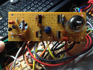
In order to check the speed of the rotation, strobe scope light was made with clock pulse.

イメージ 4

Neon lamp bulb was replaced with red LED.
イメージ 5

イメージ 6


The battery for the power amp source is supplied by two Li-po batteris (2100mAh 3cell at 11.1V/each) 
イメージ 7

The sound from the record is remarkable. Solo play tone in violin concert is very smooth and impressible. Piano tone is also vivid as if it performes live.

This turn table should not be ideal because rotor position signal with hall sensor is far from sine wave. 


(2017)

2017年4月29日土曜日

6BQ5pp DC Power amplifier IVC (電流伝送入力+pp差動出力)


After getting successful result of 6C19P Power IVC, I wanted to apply 'single tube drive' method to 6BQ5 differential push-pull power amp. The hint to get complementary two drive signals from single tube circuit is given from Hybrid Power IVC amp in MJ Audio Technology (Vol. 2016 Oct.) written by Mr Kaneta. He says in this article that "The feature of Single tube drive is not only its simple circuit but also is more natural quality of the sound".

■Circuit design
Only a half unit of duel triode 6DJ8 is used as first stage driver. Cathode voltage of the 6DJ8 is controlled by injecting variable current signal from 2SA970 so that one of grid voltage of 6BQ5 is maintained. This stabilizing circuit is called as ABC (Automatic Bias Control) in Mr.Kaneta's design.
The +90V power is supplied through regulator.

■Simulation
イメージ 2

The simulation shows reversed phase drive signals for 6BQ5 are obtained from two 2SA606.

The actual circuit is made on universal PCB.
イメージ 4

Below is 30 minutes record with data logger of grid voltage of two 6BQ5. The ABC should be working fine to get stable operating point.イメージ 3

The first impression of the produced tone from this amp is similar to one from 6BQ5 single power amp. Not so strong driving power, but clear and precise sound. Its loud sound will not be stress to the ears. The music from the speaker is vivid and natural. Single tube drive produces very remarkable result.

イメージ 5

イメージ 6

2017年3月22日水曜日

6C19P Power IVC amprifier

6C19P push pull OTL, single tube drive power IVC amplifier

This is modification from my 6C19P DC power amp. Reference is 6C33C-B power IVC amp written as an article in MJ Audio Technology, 2016 Jun. The circuit uses only 3 tubes; one WE418A and pair of 6C33C-B.

I use a WE404A and quad of 6C19P. The schematic is as shown below.

+175V for drive circuit with WE404A should be supplied through voltage regulator.

The circuit was checked with LT Spice simulation. WE404A is substituted by ECC88(6DJ8).


The drive circuit with offset control is mead on universal PCB.


Below is schematic of power supply unit. I use 'R-core Transformer (RA series)' made by Phoenix Co. (Japan based, looks very small company, but they take any order of small lot, even only one. They will make it as per purchaser's specification(primary/secondary voltage and rating) , and deliver it in around 10 days. Excellent company!)


Below is power regulators for drive circuit. The regulators start operating when timer counts up (approx. 30sec.) Rohm's MOS-FET used for regulator output control gives good performance even for such high voltage regulation. The regulators are now significant part of the amplifier circuit.
The other MOS-FETs (2SK851) on +/- 160V are just for switching power to 6C19P, which is activated by timer relay (hard timer) with 120 sec. setting, and cut off the power when amplifier output offset detection is activated.


Below is inside power supply unit.


The 6C19Ps with OTL configuration drive the loud speaker very powerful. Low tone sound is precise and rigid, and this is one of the hallmark of the series of DC power amplifiers. I feel beauty in the quality of the sound. The music from this instrument is vivid and real as if the player performs here. This is the best amplifier I have ever made. It is also interesting that combination of technologies from USA (WE404A), Russia (6C19P), and Japan (Rohm's MOS-FET) integrates hear.
(End)

2016年7月15日金曜日

6BQ5pp DC Power amp.

Differential push-pull 6BQ5 (EL84) DC power amplifier

This is modification from my 6BQ5 differential pp amp, which consists of 1st stage with 6DJ8 differential drive circuit and final with 6BQ5 differential push-pull circuit. This circuit was hinted from 'All stage differential amplifier' introduced by Tetsu Kimura. Each 6BQ5 swings under class A operation and in principle constant current flows from power supply. No AC current goes through filter capacitors. I believe this manner contributes to its clean sound.
Fig.1 6BQ5 differential push-pull power amp schematic (before modification).

The idea here for the improvement is to eliminate coupling capacitor between the stages. By introducing just one pair of PNP transistors, this was possible to realize 'direct-coupling'. I expected this DC-amplifier like circuit would improve the sound quality from this instrument to drive my loudspeakers. The most concern with this configuration is DC drift, but I tried this anyway.
The modified circuit, shown below, is made with DC-amp circuit, which directly couple 6DJ8 and 6BQ5 with 2SA606. This PNP transistors act as voltage change transmission and bias generation for the 6BQ5. The voltage gain is intentionally lowered by its emitter resistance (1.2k). The bias voltage (across 1.5k) is approx. 8.5V. VR2 (200ohm) is for adjusting these bias voltage. Additionally, CRD for first stage differential amp is changed to discrete circuit with 2SC1400.

Fig.2 6BQ5 differential pp DC power amp schematic


The feasibility of the modified circuit was tested by LT-Spice simulation as below.


Two 2SA606 are coupled with small heat sink metal so that both temperature is to be same.
(2SA606 is obsolete, of course, but still be able to buy at high price in Tokyo. Mines were used ones bought in far less price in Singapore)


Constant current discrete circuit with 2SC1400 for first stage. The 2SC1400 is very hard to get obsolete. This is also used one sold at on-line auction site.


Checking bias voltage of 6BQ5.


Oscilloscope record of bias voltage while 1kHz sine signal is fed to input.


Confirming stability of the bias. Approx 8.5V is maintained for several hours.

How is the sound?
It is much better than previous circuit and quite satisfactory because operation is so stable. Sound is also 'Rock'. This is a kind of precise sound of DC-amp. The sound quality was greatly improved by changing the transistor of constant current circuit. 2SC1400 is the best as widely known. 2SC1775A is not so good as 2SC1400, but gives average. This has been also getting hard-to-get item nowadays.

I analysed that the key to success of this circuit were:
1. Capacitor coupling was substituted by simple transistor circuit.
2. The transistor circuit was used with low gain setting and this lead to stable operation.
3. 2SC1400 is great to use here (constant current source for first stage diff amp) because this device used here affects to sound quality much.

2016年6月18日土曜日

MCイコライザIVCアンプ(電流伝送式)

MCイコライザIVCアンプ(電流伝送式)

(参照文献:金田本 「電流伝送方式オーディオDCアンプ」より、p.85 「電流出力プリアンプ&電流入力パワーアンプ」)

バッテリー駆動のプリアンプからイコライザアンプの回路をとりだして製作した。
MCカートリッジにVICアンプを内蔵し、ターンテーブルから電流伝送された信号を増幅する電流入力イコライザアンプ。差動アンプを使わないシングル構成のTr回路。±4.8Vという低電圧電源で動作する。SAOCによるオフセット制御回路により、次段のプリアンプとのカップリングコンデンサーを不要としている。


■回路図


電源は±4.8Vが指定だが、手持ち電源の関係で、±12Vにした。一部の抵抗値を変更している。MCカートリッジに内蔵する2SK97には-12Vがかかるが、最大定格電圧に対して余裕はあり問題はない。


■シミュレーション

VICアンプの2SK97のSPICEモデルがないので2SK170GRで代用する。ここに4mAほど流れるのでISCで3mA流れるようにR3を調整するとSAOCから1mAくらいが注入されることがわかる。

ついでに周波数特性もシミュレーションしてみた。 30Hzあたりより下でゲインが下がっているのはSAOCの影響らしい。


■製作
1) 基板


2) MCカートリッジ + VICアンプ(2SK97)

カートリッジのピンに直接半田付けする勇気はなかった。


■調整

最初にISCとSAOCの配線を外した状態でTr3のベース抵抗を調整して出力オフセットをゼロにする。この抵抗値は初段の2SK117BLのIdssによってかなり違うようだ。だいたいゼロに近ければよい。次にISCとSAOCの配線を戻し、入力に調整用VICを取り付ける。そしてSAOCの出力Tr.の3.6kΩの電圧降下を測り3.6VになるようにISCのVRを調整する。ISCの2SJ103はIdssが2SK97の電流くらい流れるものを使わないとうまく調整できない。調整後のVRは100Ωより低いのでVRは200Ωでもよかった。

↓調整用VIC (2SK97のGS間はショート状態にする)


■完成


電池はNi-MH(eneloop)が指定だが、手持ちのLiPo(3セル)を使った。いずれはeneloopに交換しよう。

真空管プリアンプ(ラインアンプ)につなぐ。カップリングコンデンサ(0.1μF)は撤去した。
パワーアンプの出力トランスでスピーカへのDCはカットされているのでDC漏れは気にならないが、聞いた感じもゴロつきは心配ないレベル。針がレコードの溝をこする振動がダイレクトにスピーカを鳴らしてくる感覚が格段に高まった。これは異次元のレコード再生音だ。
LPのコレクションはあまりないが、数年前に中古本屋で買っておいたLP(一枚 $2~3)を引っ張り出してきた。Vnのソロは弓が弦の上をはねるときの表現とか高音の倍音がたくさん聞こえてくるのでもっと聞きたくなる。意外なのはこれまでレコード再生は難しいと思っていたピアノの音。弦をたたくアタック音がガツンと感じられ、高い弦に響いている余韻がわかる。演奏者の芸術をレコード盤に封じ込めた当時の録音技術者に感謝したくなる。アナログ再生の良さを見直そう。 

次に欲しくなってくるのはカートリッジの針の振動のパワーを作っているターンテーブルのモータのDCアンプ制御だ。